General description:
Davis Vantage Pro Weather Station UV Sensor troubleshooting and repair
Functional description:
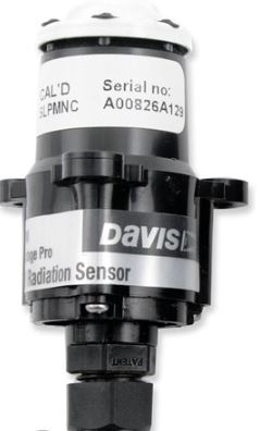
Vantage Pro Weather Station uses an UV detector assembly connected to a sensor interface module. Sun's UV intensity is displayed as an UV- index on a scale 0 to 16, where 16 corresponds to 2.4 V output (150 mV / UV index).Original sensor spectral response covers wavelenths from 280 to 360 nm.
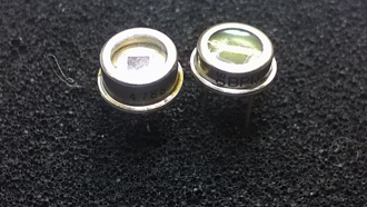
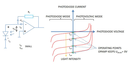
UV sensor is a semiconductor photodiode of undefined origin.When in operation, sensor acts as a current source and its current is transformed into voltage in the first amplifier of a rail-to-rail op amp TLV2472A. First amplifier produces a negative going signal therefore a voltage inverter for the opamp negative supply is required. This is implemented by using a SOT23-5- packaged MAX 828 EUK. Second amplifier stage of the TLV2472A is an inverting amplifier with 500 kohm trimmer potentiometer adjustable amplification. The other 500 k potentiometer if for fine adjusting the DC offset.
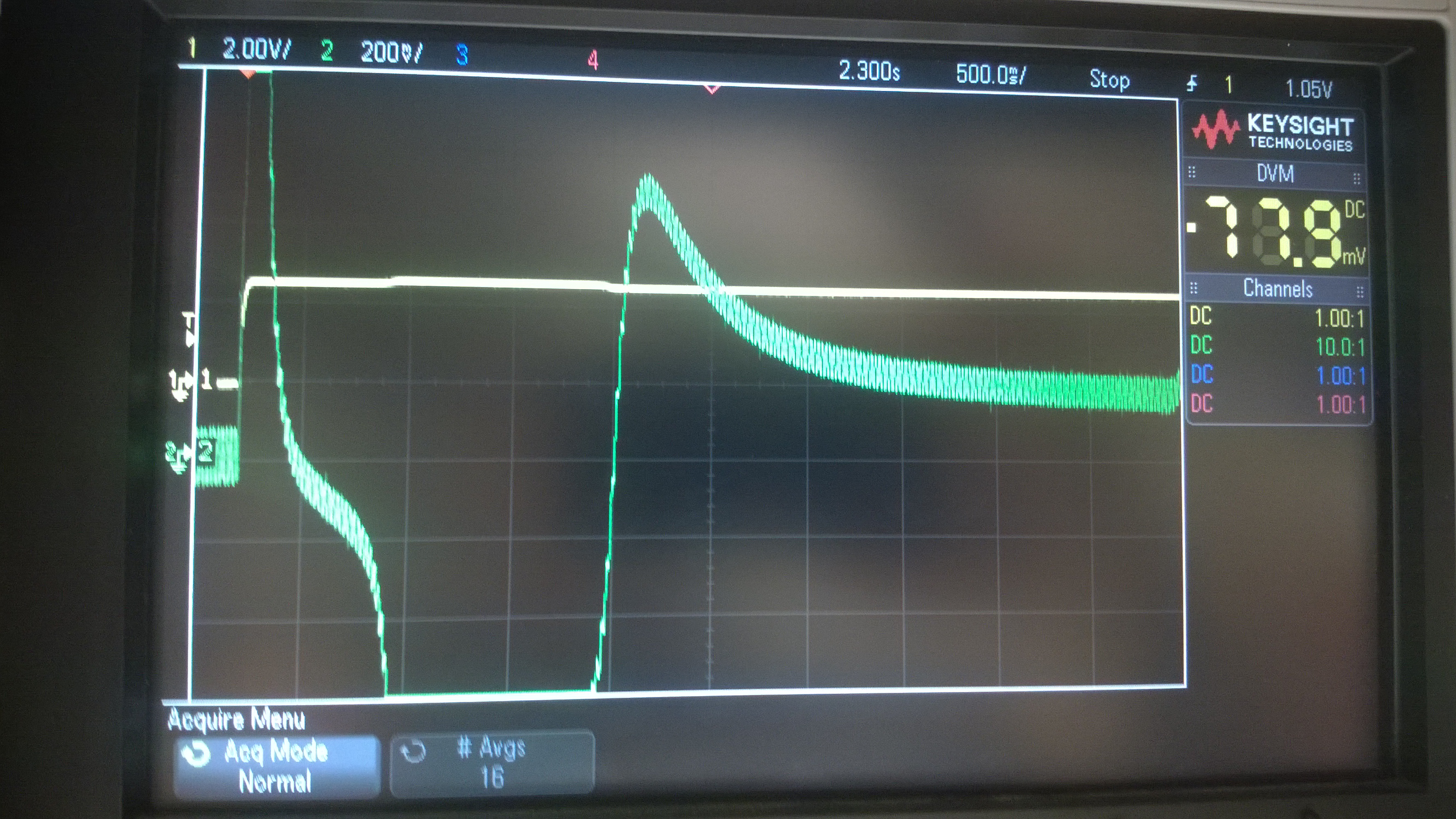
Sensor interface module pulses the supply voltage +3V of the UV sensor. On-time is 2.3s and off-time depends on the solar radiation (another sensor in the Vantage Pro unit). On strong sunshine the pulsing happens about once a minute, at other times less frequently (off- time is several minutes)
Fault symptoms: UV signal appears only occassionally and appears to be low even in strong sunshine.
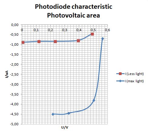
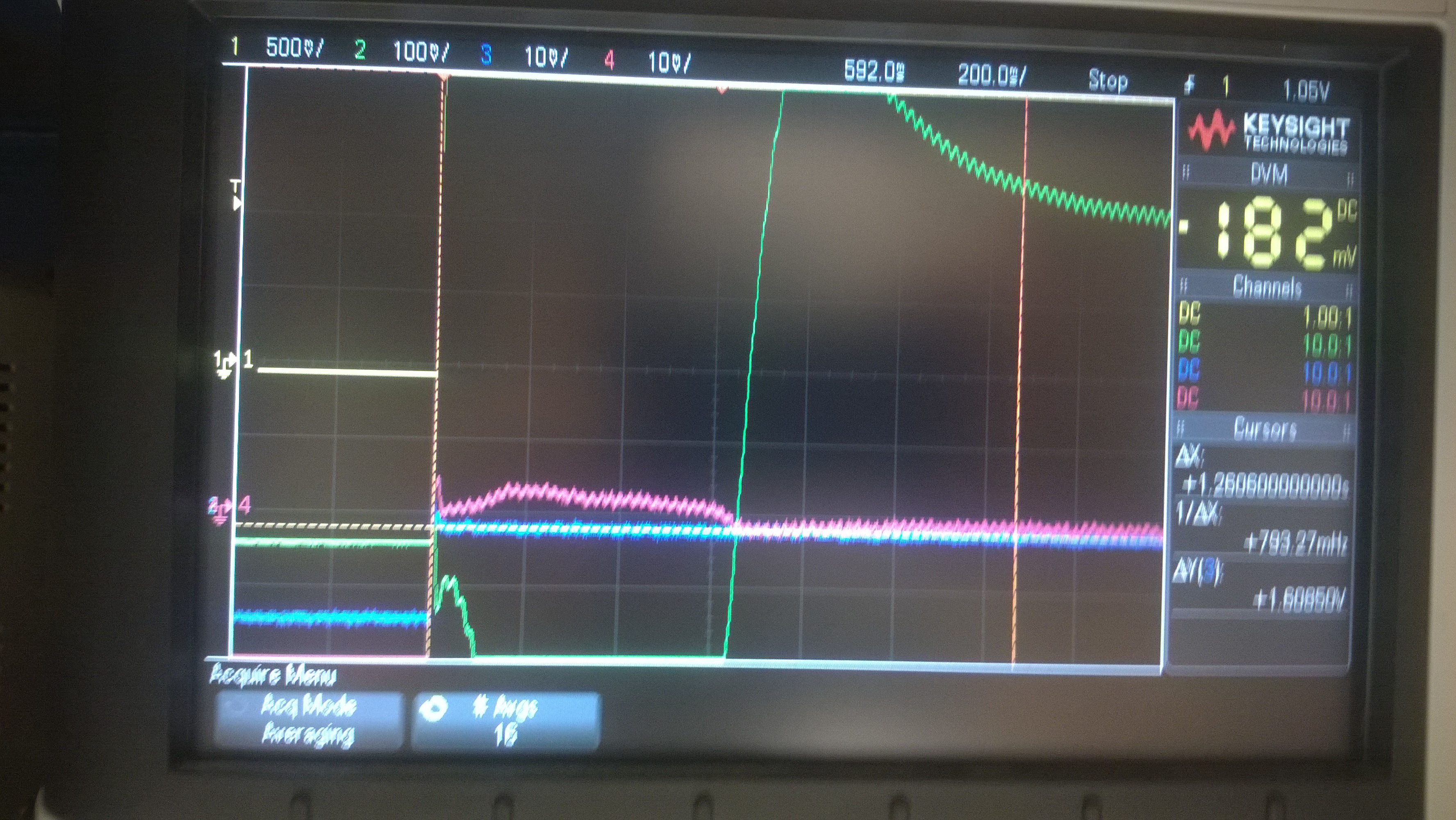
Findings: Signal from the second amplifier stage remains negative for almost two seconds after supply voltage pulse rising edge. The second amplifier is driven into negative saturation, due to its large gain of about 370, because amplifier 1 output goes positive a few millivolts for a while (pink trace), which biasing circuit in amplifier 2 cannot compensate within its positive input trimming range of +/-1.8 mV, set by voltage divider 511k / 300 ohm. Saturation (due to photo diode voltage negative excursion) seems to depend on the temperature of the photo diode or the associated circuitry. When cold, the recovery takes under 500 ms but after a while in sunshine, the signal delay is too long, and may not become positive at all during the 3V supply voltage pulse and cannot be detected by the Sensor Interface Unit which reads the output of the sensor close to the end of supply voltage pulse (in about 2 seconds).
Repair/Workaround: Change the photo diode and readjust the gain in the second amplifier based on local UV index information in the internet. Result may not correspond exactly the original calibration of the sensor unit, but could be justified for a hobbyist when the replacement unit cost over 350 euros seems to be prohibitively high. In addition, if the design remains the same in the new sensor, this phenomenon is likely to reappear at some point of time. The best fix would be to add features to the circuit that clamp the amplifier output from going too near to either of the rail voltages.
I used a BPW21 and short circuited the 150k in the feedback loop, readjusting 500k gain trimmer as required.